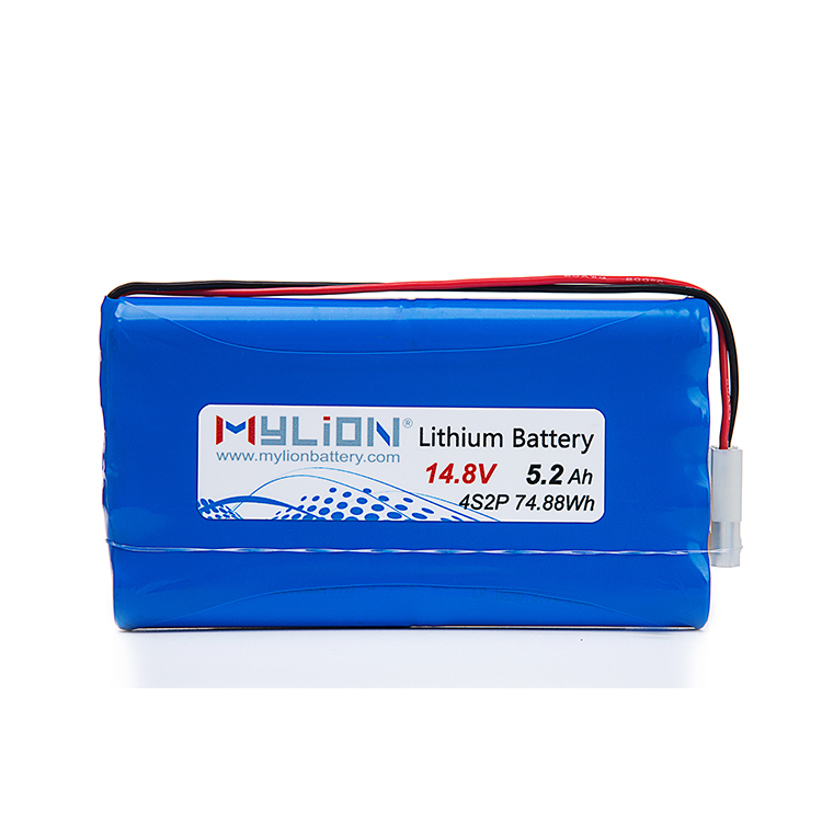
Description
How to Evaluate Battery Pack Voltage Drop Under Load
For engineers and product teams designing battery-powered equipment, voltage drop under load is one of the most consequential and frequently underestimated performance variables. When a battery pack delivers power to a real device, the terminal voltage does not remain static—it falls in response to current demand, internal resistance, temperature, and cell chemistry. Misunderstanding or ignoring this behavior is a primary cause of device malfunction, BMS protection trips, premature shutdowns, and costly redesign cycles. This article provides a structured methodology for evaluating voltage drop under load, with particular attention to how proper engineering practice—as advocated by custom battery specialists like MYLION—can prevent the most common project failures.
Understanding What Voltage Drop Under Load Actually Means
Voltage drop under load refers to the difference between a battery pack’s open-circuit voltage (OCV) and its terminal voltage when current is actively flowing to a connected device. This drop is governed primarily by the pack’s internal resistance (IR), which includes contributions from the cell chemistry, electrode-electrolyte interfaces, interconnects, BMS circuitry, and connector paths.
The relationship is expressed simply as:
Voltage Drop = Load Current × Internal Resistance
However, in practice, the relationship is nonlinear. Internal resistance increases as cells age, as temperature drops, and as state of charge (SOC) approaches the lower threshold. This means voltage drop behavior changes across the full lifecycle of a pack, and evaluating it only at nominal conditions provides an incomplete picture.
Why Voltage Drop Evaluation Must Be System-Specific
A critical mistake in battery pack selection is evaluating voltage drop in isolation—measuring a pack’s behavior on a resistive load bench without replicating the actual device demand profile. Real devices, especially in industrial robotics, IoT systems, and field equipment, impose dynamic load profiles with significant peak-current events. A motor startup, a wireless transmission burst, or an actuator engagement can draw three to five times the continuous current rating for milliseconds to seconds.
These transient peaks cause instantaneous voltage dips that may cross a device’s minimum operating threshold or trigger the BMS under-voltage protection, cutting off power mid-operation. Evaluating voltage drop only at steady-state continuous current will miss this class of failure entirely.
This is precisely why industry practitioners emphasize that battery pack evaluation cannot be separated from the full system context. The load curve, power architecture, BMS threshold settings, and minimum device operating voltage must all be defined and confirmed before meaningful voltage drop assessment can take place.
A Structured Approach to Evaluating Voltage Drop Under Load
Step 1: Define the Full Load Profile
Before any electrical measurement, the actual device load profile must be documented. This includes:
- Continuous current draw during normal operation
- Peak current magnitude and duration during startup or high-demand events
- Duty cycle — the percentage of time spent at peak versus idle
- Minimum acceptable terminal voltage for the device to function correctly
Without this baseline, no voltage drop evaluation can be considered valid or repeatable.
Step 2: Measure Internal Resistance Accurately
Internal resistance should be measured using an AC impedance method or pulse discharge method, not a simple DC resistance test, which tends to understate true dynamic impedance. The measurement should be taken at:
- Multiple SOC levels (100%, 80%, 50%, 20%)
- Multiple temperatures reflecting the device’s operating environment
- Both fresh and aged cell states if lifecycle performance is relevant
This multi-dimensional IR profile gives engineers the data needed to model worst-case voltage drop across the pack’s service life.
Step 3: Simulate Real Load Conditions
Using the load profile defined in Step 1, apply a programmable electronic load configured to replicate the dynamic current waveform of the actual device. Record terminal voltage continuously, paying particular attention to:
- Voltage nadir during peak current events — the lowest point reached
- Voltage recovery time — how quickly the terminal voltage rebounds
- Cumulative sag over extended discharge cycles
This step should be performed at the pack’s minimum rated operating temperature, since cold conditions significantly elevate internal resistance and worsen voltage drop behavior.
Step 4: Validate BMS Protection Thresholds Against Real Load
BMS under-voltage cutoff thresholds must be reviewed in relation to the measured voltage drop profile. If the measured terminal voltage during a legitimate peak load event dips below the BMS cutoff threshold, the system will shut down even though the pack has adequate remaining energy. This mismatch between BMS configuration and real load is a documented source of field failures in industrial and professional equipment.
Engineers must confirm that the BMS thresholds are set with sufficient margin to distinguish between a genuine under-voltage condition and a transient voltage dip caused by normal peak load demand.
Step 5: Confirm Series/Parallel Architecture Compatibility
For multi-cell configurations, series/parallel architecture directly affects both voltage and current capability. A pack configured with more cells in parallel reduces effective internal resistance per channel, thereby reducing voltage drop at equivalent total load. Confirming that the cell architecture is matched to the required discharge rate—not just the nominal energy capacity—is an essential and often overlooked part of the evaluation.
How Engineering-First Suppliers Reduce Voltage Drop Risks
The systematic steps outlined above require a supplier that treats battery packs as engineered components embedded within a larger system, not as commodity items selected by catalog. Shanghai Mylion New Energy Co., Ltd., operating under the brand MYLION, structures its custom battery pack development around exactly this requirement.
MYLION’s project model begins with requirement engineering—converting real device inputs, including peak load, runtime, BMS function needs, connector specifications, and operating environment constraints, into reviewable technical specifications. The company performs electrical architecture review to determine the correct series/parallel cell configuration from energy and runtime targets, and explicitly addresses load matching by aligning both continuous and peak current ratings to the actual device load.
For customers working with LiFePO4, 18650/21700 cylindrical cells, or LiPo formats, MYLION validates that the selected chemistry and physical configuration can meet the full dynamic load demand—not just the steady-state spec. BMS matching is treated as an integrated design decision, with protection thresholds, balancing behavior, and communication functions reviewed relative to the actual operating profile before samples are produced.
This engineering methodology directly prevents the most common voltage drop-related failures: BMS trips during legitimate peak loads, thermal issues from undersized discharge paths, and connector or interface voltage losses that degrade system performance over time.
Final Considerations for Battery Pack Teams
Evaluating battery pack voltage drop under load is not a single-point test—it is a multi-condition, system-integrated assessment that spans cell chemistry, BMS configuration, pack architecture, and real device demand. Teams that approach this evaluation rigorously, and partner with suppliers capable of supporting that rigor through structured engineering processes, significantly reduce the risk of field failures and production redesigns.
For B2B equipment manufacturers, product brands, and system integrators facing complex battery integration requirements, working with an engineering-oriented partner like MYLION provides a structured path from requirement definition through validated production-ready specifications—addressing voltage drop and related risks as part of a controlled, repeatable development process.
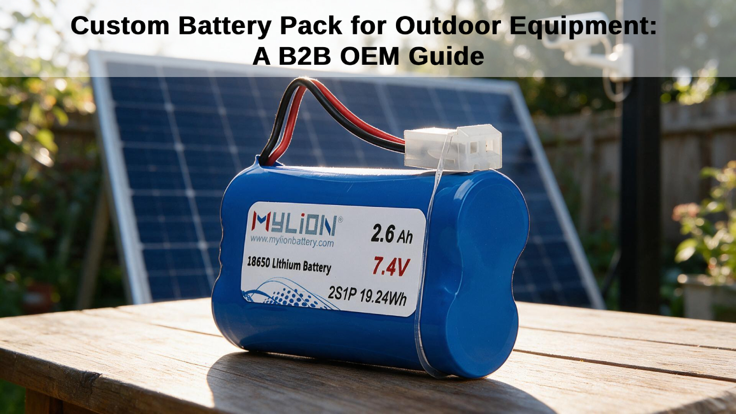
More information about MYLION’s custom battery pack engineering capabilities is available at www.mylionbattery.com.


Reviews
There are no reviews yet.